

Since its invention by C. Rice and E. Kellogg in 1925 [1], the electrodynamic loudspeaker has been more than widely exploited in the audio industry. But if we come to discuss the means of predicting its acoustic behavior, it is rather when L. Beranek published his book Acoustics in 1954 [2][3] that the first models (based on the principle of Lumped elements [4]) were popularized. Among the electroacoustic parameters listed by Beranek in his book (also formulated by A. Thiele and R. Small at the same era), here are the fundamental ones:
– 𝑅𝑒, the electrical resistive part of the voice coil, in ohms,
– 𝐿𝑒, the electrical inductive part of the voice coil, in millihenries (often at 1k Hz),
– B.l, the product of magnet field strength in the voice coil gap and the length of wire in the magnetic field, in tesla-meters,
– 𝑀𝑀𝑆, the mass of the assembly “diaphragm / voice coil”, the mass of half of the outer suspension and the mass of air particles around the diaphragm (that becomes non-negligeable when dealing with small sized speakers), in kilograms,
– 𝑅𝑀𝑆, the mechanical resistance of suspensions, in Newton-second per meters,
– 𝐶𝑀𝑆, the total mechanical compliance of suspensions, in meter per Newton,
– 𝑆𝐷 (mentioned in the form of the radius “a” in the Beranek’s book), the projected area of the speaker diaphragm.
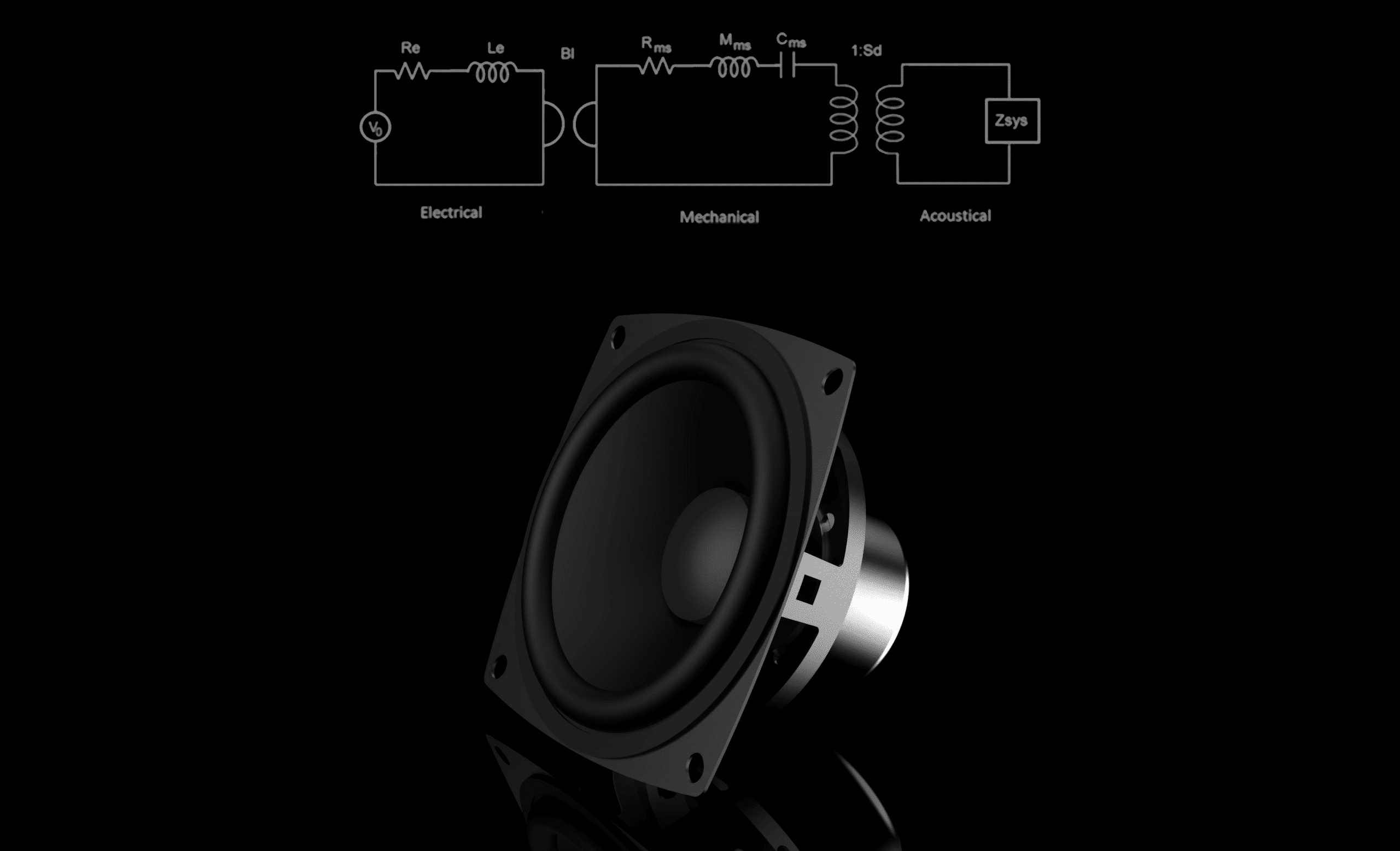
In his book, Beranek also helped popularize the electrical network that defines the electro-mechano-acoustic behavior of such a loudspeaker. The diagrams in Figure 1 present three loops, dealing respectively with the electrical, mechanical, and acoustic domain of the transducer.
Among important analogies brought by this circuit, ones to save in mind are:
– Voltage (U) from the first loop becomes a mechanical force (F) in the second loop and an acoustical pressure (P) in the third loop,
– Current (i) from the first loop becomes a mechanical velocity (v) in the second loop and an acoustical flow (q) in the third loop.
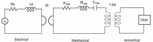
In this circuit, the link between the loop No. 1 and 2 is ensured by a gyrator. This later defines the following relationship F = B.l * i ; U = B.l * v . The link between the loop No. 2 and 3 is achieved through a transformer. This later defines the following relationship P = F/SD
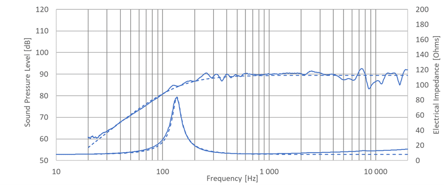
It is important to note that this modeling approach assumes one-dimensional acoustic behavior only. There is therefore an upper frequency limit for the validity of this model, which we can approximate as its quarter wavelength being comparable to the size of the diaphragm of the loudspeaker considered.
The Figure 2 below illustrates an example around a 45 mm dia. loudspeaker, where measurements are compared to simulations. From this comparison, we observe a very good matching of the predictions until the theoretical frequency limit of 1.9 – 2k Hz. Above this frequency, radiation from the loudspeaker slowly starts to be impacted by the resonances from the diaphragm itself.
By adding a few components to the model presented in Figure 1, it then becomes possible to simulate the impact of a rear volume or a front cavity on the speaker sound signature.
Seltech can help you simulate your system and refine each parameter to offer you an acoustic solution that precisely meets your requirements.
Review by:
Frédéric Fallais, Acoustic Application Engineer
Arthur Di Ruzza, Acoustic Technician
Sources :
[1] C. W. Rice and E. W. Kellogg, “Notes on the Development of a New Type of Hornless Loud Speaker,” Transactions A.I.E.E., 1925, Vol. XLIV
[2] L. L. Beranek, Acoustics, Massachusetts: Institute of Technology, 1954
[3] L. L. Beranek and T. Mellow, Acoustics: Sound fields, Transducers and Vibration (Second Edition), Academic Press, 2019
[4] https://en.wikipedia.org/wiki/Lumped-element_model
[Fig.1] J. Hipperson et al. Multiphysics simulation of a low frequency horn loudspeaker, Institute of Acoustics, Reproduced Sound 2021